Bridge Software Institute FB-MultiPier 5.5 | 261.1 mb
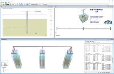
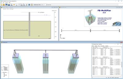
Bridge Software Institute is pleased to announce the availability of FB-MultiPier 5.5, is a nonlinear finite element analysis program capable of analyzing multiple bridge pier structures interconnected by bridge spans.
Major features include:
- Option to rigidize pile top portions.
- AREMA load combinations for rail bridges.
- Customized Design Table output.
- Multiple-support excitation for nonlinear dynamic seismic analysis.
Program »
Enhancements: Implemented AREMA load combinations and interaction diagrams for use in applications pertaining to railway bridges.
Program »
Enhancements: Added option to rigidize top portions of piles (e.g., within pile cap thickness).
Program »
Enhancements: Implemented user-defined nodal coincidence tolerance for pier/bent cap node generation.
Program »
Enhancements: Added option to disable Georgiadis layer corrections for layered soil profiles.
Program »
Enhancements: Added option for automatic calculation of p-multipliers during analysis.
Program »
Enhancements: Added option to apply unique axial skin friction group factors for upward and downward pile motions.
Program »
Enhancements: Implemented multiple-support excitation for use in seismic applications.
Program »
Enhancements: Added option for nonlinear elastic treatment of steel for time-history analysis.
Program »
Enhancements: Added option for lumped mass formulation for time-history analysis.
Program »
Enhancements: For nonlinear dynamic vessel collision analysis, added ability to define collapse mechanisms.
Engine »
Enhancements: For nonlinear dynamic vessel collision analysis, added calculation of proximity to collapse.
Engine »
Enhancements: For substructures that undergo displacements with both X and Y components, the p-y spring evaluation algorithm was updated such that each p-y spring aligns with the resultant displacement direction of the respective embedded pile node as part of the analysis. See the Spring 2019 Newsletter for additional details.
Engine »
Enhancements: For minimum pile tip embedment analysis, added prints of corresponding load case (or combination) to .PEL post-processing file.
Engine »
Enhancements: Added XML output of contents under SPANLOAD header.
Engine »
Enhancements: Added output file (.OUT, .XML) prints for pile to pile cap fixity.
Engine »
Enhancements: Added output file (.OUT, .XML) prints of bearing summary forces.
Engine »
Enhancements: Increased maximum number of time steps for time-history analysis to 19,999 steps.
Engine »
Class 3: For bridge models containing rotated substructures and use of lateral-axial coupling of soil resistance forces, corrected processing of coupling forces. Prior to this correction, convergence was not possible.
Engine »
Class 3: For pushover models that contain springs, corrected reading of enable/disable springs flag so that it is respected across all load steps.
Engine »
Class 4: For confined concrete models with casing but low reinforcement ratios (
Engine »
Class 4 Corrected pier/bent cap node generation for instances when a non-movable node was positioned between a pad offset and a candidate movable node.
Engine »
Class 5: For instances where the auto-check of the number of distinct pile types versus defined soil sets is disabled, changed the log file notification from "WARNING" to "NOTE".
Engine »
Class 5: Changed output file (.OUT, .XML) format of bearing force prints to scientific notation.
Interface »
Enhancements: In Design Tables, added option to choose specific load cases / combinations / time steps from which data are reported.
Interface »
Enhancements: In Soil Edit window, added interactive elevation line, option to display node numbers, and improved aesthetics of elevation labeling alignments.
Interface »
Enhancements: In Bridge Span Force Description dialog, added table to display Description values and option to export to Excel / PDF.
Interface »
Enhancements: Added All | None selection controls to facilitate ease of data entry on several dialogs, including the Springs page, Analysis Settings (print control), PreLoad dialog, Thermal dialog, Surcharge dialog, and MPTE dialog.
Interface »
Enhancements: In the Pile Plan View window, added option to only display soil set assignments at locations where a pile is present.
Interface »
Enhancements: In the License Wizard and About dialog, added clipboard options to facilitate license updating.
Interface »
Enhancements: In the Pile Plan View window, added option to deselect piles using a drag box.
Interface »
Enhancements: Created new icons for the title bars of numerous windows to help indicate the purpose of said windows.
Interface »
Enhancements: On the Soil page, implemented hand icon when mouse hovers over the soil layer model types (Lateral, Axial, Torsion, and Tip) to better indicate that these items are clickable.
Interface »
Enhancements: Improved and simplified navigation in various windows, including enabling the bearing layout controls for bridge models on the Bearing Locations dialog, moving soil behavior controls from the Analysis Settings page to their own window, and removing the Generated Load History from the Load Generator dialog.
Interface »
Enhancements: Improved detection of need for vertical scrollbar on windows that approach full height of screen to avoid cutting off portions of relatively tall dialogs.
Interface »
Enhancements: In the Soil Edit window, improved the display of pile segment widths, and improved the positioning alignments and aesthetics of various elements in the window (soil property labeling, elevation labeling, model position when soil is above the pile cap midplane).
Interface »
Enhancements: Added error checking to improve modeling as follows: on Pier page and Bent Cap page, added option to remove bearings that no longer fit on pier cap / bent cap due to changes in pier cap / bent cap length; on cross section dialogs, stop allowing default cross sections to be deleted from database, in 3D View window when selecting nodes for extra members and for stiffness node, added message boxing when midside (or center) shell element nodes are selected; when using auto-generation of load combinations, constrained the adding and deleting of load cases to the Design Spec page, on Model Page when converting model, added list of allowed model type conversions.
Interface »
Enhancements: Improved labeling clarity in various windows, including using substructure type specificity on Bridge page Substructure pulldown list and Substructure dialog bar, Design Spec. and Dynamics specific labeling on the Pile Cap Forces dialog, increased robustness in analysis stage in Analysis window, soil property name change for some t-z and q-z properties, and suffixed all files with _BPF when conducting span self-weight loading analysis for bridge models, implemented same span element numbering system to be consistent with system used in the output (.out) file.
Interface »
Enhancements: Improved responsiveness on Pile Cap page when pile grid mesh is modified to a 1 x 1 mesh.
Interface »
Class 3: When using the AASHTO module, and 10 or more load instances were defined for any of live load (LL), impact (IM), braking (BR), wind on structure (WS), or wind on live load (WL), load instances at 10 or beyond could be ignored during subsequent reloads of the input file. This issue has been corrected.
Interface »
Class 3: On certain machines, recent operating system (OS) updates led to crashes when engineers attempted to point-select graphical objects within 2D graphical windows. This issue has been overcome so that crashes no longer occur despite the recent OS updates.
Interface »
Class 3: Fixed issue on Description Display Control dialog when AASHTO LFRD or LFD is used, whereby the 'Max D/C Ratio For Limit State' output control was in some cases not reporting the correct D/C ratio for structural elements.
Interface »
Class 3: Fixed issue with AASHTO LFD when ICE (Ice Load) is present in model whereby custom (user-defined) factors could be overwritten during input file read.
Interface »
Class 3: Fixed display issue in 3D View window in hammerhead models for instances when the element numbering display was incorrect.
Interface »
Class 3: Fixed issue in Full Cross Section Pier Component Properties dialog whereby column cross sections would not allow bullet orientation along the local (2) axis.
Interface »
Class 3: Fixed issue in bridge models using staged analysis options, but where the first analysis stage was not able to reach convergence.
Interface »
Class 3: Fixed issue on Load Factor dialog where VP and VR were assigned default factors not consistent with AASHTO specification used for all other load factors.
Interface »
Class 3: Fixed issue on Load Case Manager dialog for LFD design code where number of instances of WL (Wind on Live Load) should not have affected the number of allowed instances of WS (Wind on Structure), and vice versa.
Interface »
Class 3: Fixed issue on Load Case Manager dialog for LFD design code where number of instances of CF (Centrifugal Force) were allowed to exceed the number of instances of LL (Live Load).
Interface »
Class 4: Fixed issue on 3D Display Control dialog for pile bent models that use modal response analysis, where mode shape option was disabled in some cases and when it was enabled, nodes on pile bent did not draw in 3D Results View window.
Interface »
Class 4: Fixed crash issue on input file open, if previously, the file was closed via the Close menu item and the Description Display Control dialog was subsequently visited.
Interface »
Class 4: Fixed the following display issues that affected high-resolution screens: on Printable Forces dialog, the table columns were in some cases too narrow, and on the Surcharge dialog the image for Uniform Surcharge was not displayed.
Interface »
Class 4: On dialogs with tables, disabled drag and drop option.
Interface »
Class 4: Fixed issue on Edit Load Functions dialog and Load Table dialog where in some cases, negative load magnitudes were not allowed to be input.
Interface »
Class 4: Fixed display issue in Edit Load Functions dialog where some curves were cutoff at the top of the Description area.
Interface »
Class 4: Fixed display issue in 3D Bridge View window for One-Pier Two-Span (OPTS) models where a non-zero pile cap elevation was not being accounted for in the positioning of springs, masses, and span tip nodes.
Interface »
Class 4: Fixed display issue in 3D Pile Element Selection window and 3D Pier Member Selection window where window view needed to be reset when opening a new input file.
Interface »
Class 4: Fixed display issue in Bridge Plan View window where rightmost substructure was sometimes cutoff at right edge of window if pier rotation was applied.
Interface »
Class 4: Fixed display issue in 3D Results View window for OPTS models, where model wasn't vertically centered by default if pile cap midplane elevation was non-zero.
Interface »
Class 4: Fixed issue for Retaining Wall models on Pier Cross Section Table dialog where Wall Taper option should have been disabled.
Interface »
Class 5: Fixed display issue in 3D View window where some models with battered piles would flicker momentarily when model was modified from no free length to a free length being present.
Interface »
Class 5: Fixed labeling issue in Design Tables in which time step label was used in place of load case label.
Interface »
Class 5: Fixed issue with Pier Cap Moment Design Table not generating when fatigue limit state was present in model.
Interface »
Class 5: Fixed crash when opening an input file that contained a model not permitted by program license when said model was opened by means other than using the file menu or open file button on the toolbar.
Interface »
Class 5: Fixed crash when cancelling out of printing a program window via the print button on the toolbar.
Interface »
Class 5: Fixed issue with option to show/hide messaging for soil sets vs. pile batter / type configurations not being respected.
x Bridge Software Institute FB-MultiPier 5.5
Close
About FB-MultiPier. FB-MultiPier is a nonlinear finite element analysis program capable of analyzing multiple bridge pier structures interconnected by bridge spans. The full structure can be subject to a full array of AASHTO load types in a static analysis or time varying load functions in a dynamic analysis. Each pier structure is composed of pier columns and a cap. This structure is supported on a pile cap and piles/shafts with nonlinear soil. This analysis program couples nonlinear structural finite element analysis with nonlinear static soil models for axial, lateral and torsional soil behavior to provide a robust system of analysis for coupled bridge pier structures and foundation systems. FB-MultiPier performs the generation of the finite element model internally given the geometric definition of the structure and foundation system as input graphically by the designer. This allows the engineer to work directly with the design parameters and lessens the bookkeeping necessary to create and interpret a model. As is a necessity for design-oriented applications, FB-MultiPier automatically generates finite element models given a parametric, geometric definition of the structure and foundation system. Both input and analysis results are handled through a streamlined combination of form-based, 2D graphics, and 3D graphics windows.
About Bridge Software Institute. The mission of the Florida Bridge Software Institute is to bridge the efforts of the research community and the transportation industry by providing software, software maintenance, technical assistance and training to states DOT's and industry professionals. This will be accomplished primarily by starting from the Department of Civil Engineering, University of Florida research projects and further refining the resulting efforts into products in a form that is easy to disseminate. The software upkeep, upgrading and improvements for general use will be the major efforts of the institute. The Florida Software Bridge Institutes customers include many of the DOT's in the nation as well as most of the consulting firms that work on bridge design and anaylsis.
Product: Bridge Software Institute FB-MultiPier
Version: 5.5
Supported Architectures: 32bit / 64bit
Website Home Page :
https://bsi.ce.ufl.edu/
https://bsi.ce.ufl.edu/
Language: english
System Requirements: PC
Supported Operating Systems: Windows 7even or newer
Size: 261.1 mb
Recommend download скачать Link Hight Speed | Please Say Thanks Keep Topic Live
Uploadgig
https://uploadgig.com/file/download скачать/2565c1bf31EAE259/424pz.Bridge.Software.Institute.FBMultiPier.5.5.rar
Rapidgator
https://rapidgator.net/file/3c29803903071e14b71e04d17ea0de81/424pz.Bridge.Software.Institute.FBMultiPier.5.5.rar
NitroFlare
https://nitroflare.com/view/F713D5688C0E346/424pz.Bridge.Software.Institute.FBMultiPier.5.5.rar